LibrePCB
LibrePCB is a free and open source electronics design automation (EDA) software suite to develop printed circuit boards (PCBs). It runs on all major platforms and aims to be easy to use, while still beeing able to create professional schematics and PCBs. The goal is to make creating electronics easier, more efficient and less error-prone by using modern technologies and user interface concepts. LibrePCB therefore streamlines the whole PCB design process — from installing part libraries to ordering the final PCB design. Having such a free, powerful EDA software is the basement for the whole open hardware community as it allows us to reduce the dependency to proprietary and expensive technologies and empowers everyone to develop hardware for free, from hobbyists to professionals.
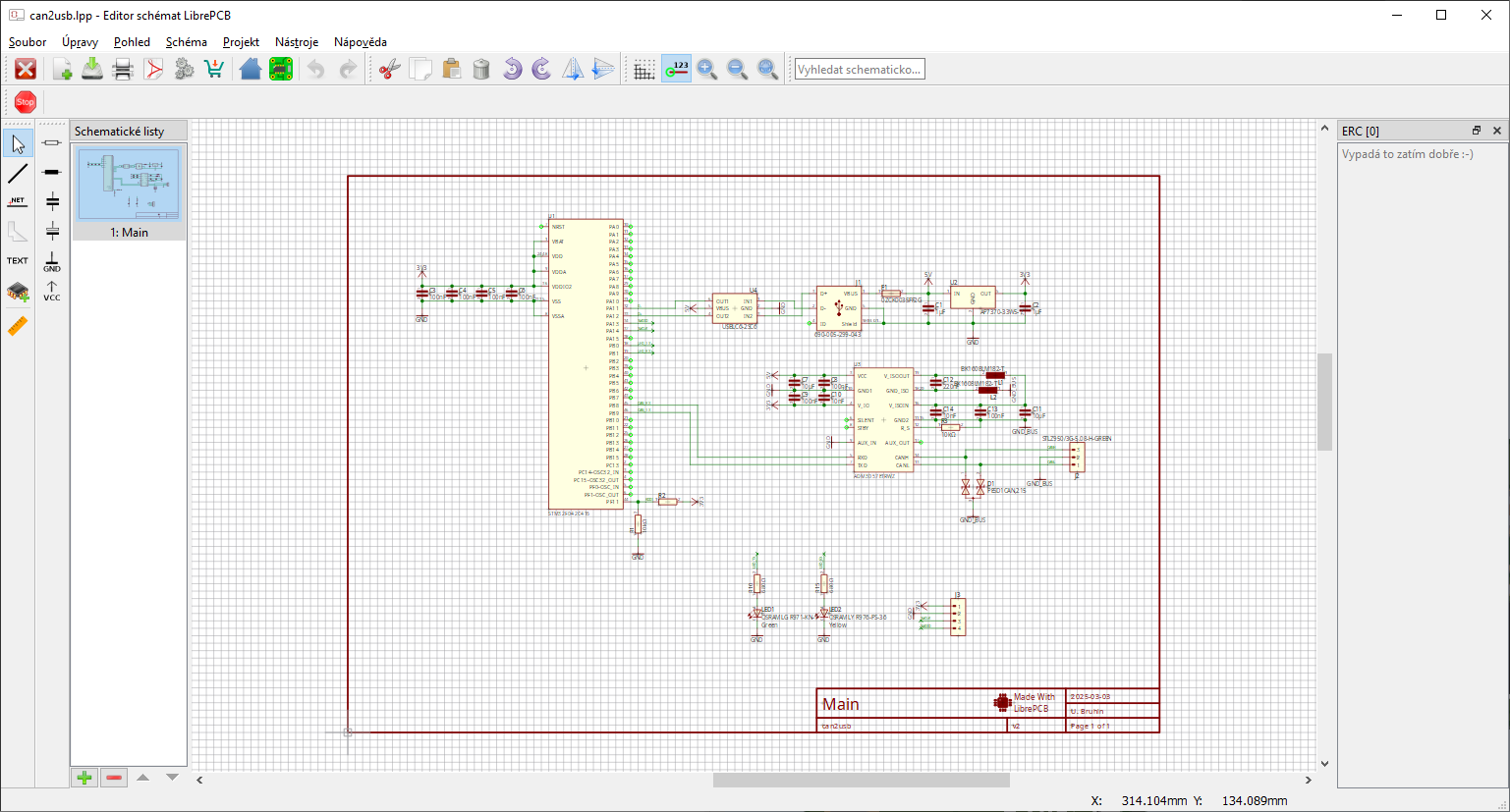
Schematic Editor Features
LibrePCB is a lightweight open-source PCB design tool with a schematic editor that prioritizes simplicity and ease of use. While not as feature-rich as Altium Designer or KiCad, LibrePCB provides a clean and modern interface for quick schematic capture, with essential functions such as ERC checking and hierarchical design support. Its library management system is designed to be intuitive and user-friendly, reducing the complexity often associated with component handling in other tools. However, LibrePCB currently lacks some advanced features like SPICE simulation and deep integration with external verification tools, making it better suited for small projects, hobbyists, and beginners rather than large-scale professional designs. An example of how the schematic editor GUI looks like in KiCAD environment is shown in the following Figure.
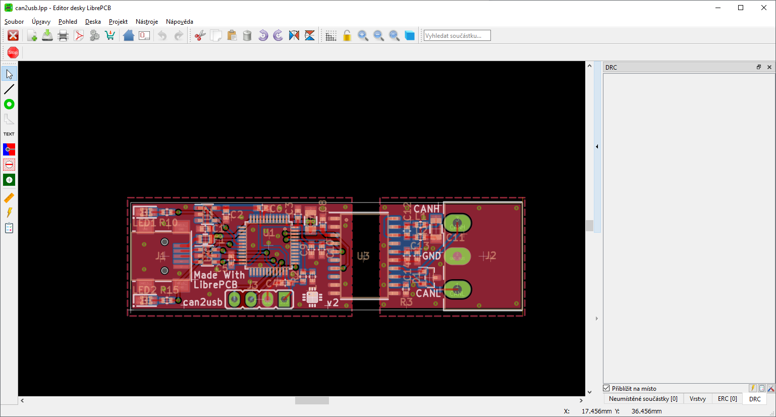
PCB Layout Editor Features
LibrePCB offers a simpler yet effective PCB layout editor, designed for ease of use and quick prototyping. While it does not provide as many advanced features as Altium or KiCad, it supports essential functions like basic multi-layer routing, component placement, and design rule checks (DRC) to ensure manufacturability. LibrePCB focuses on providing a streamlined workflow, allowing users to quickly transition from schematic to PCB layout without dealing with extensive settings or configuration steps. However, it currently lacks features such as differential pair routing, impedance control, and advanced high-speed design support, making it more suitable for beginners, hobbyists, or small-scale projects rather than complex professional applications. An example of how the PCB editor GUI in action like in LibrePCB tool is shown in the following Figure.
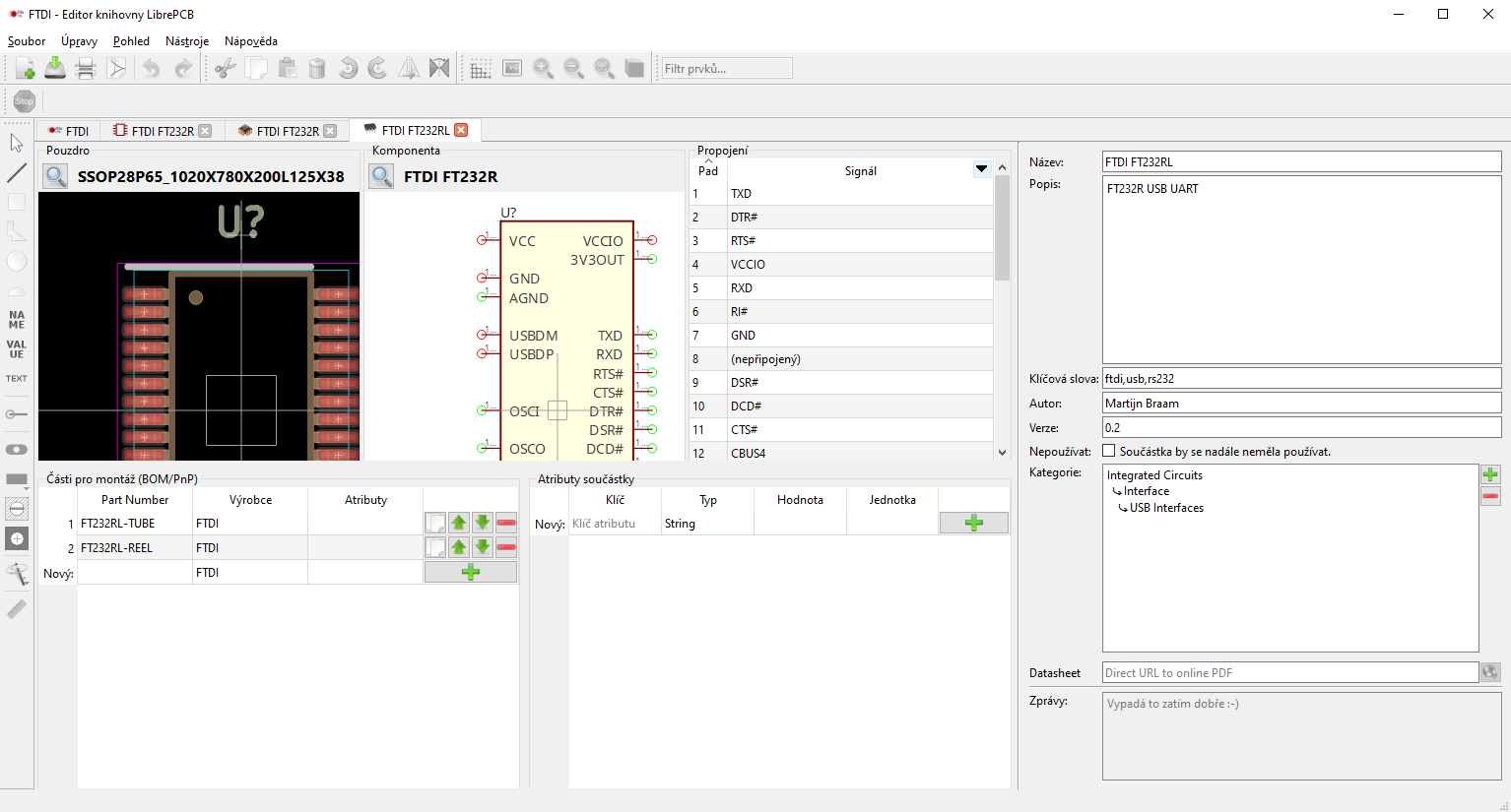
Components Libraries and Management
LibrePCB focuses on simplicity and ease of use when managing and creating component libraries. Unlike KiCad and Altium, LibrePCB unifies symbols, footprints, and metadata into a single entity, streamlining the process of defining components. The Library Manager allows users to create and edit components using a guided workflow, reducing complexity for newcomers. LibrePCB also introduces a unique library repository system, enabling users to install libraries directly from online sources rather than manually downloading and importing files. However, the selection of pre-existing libraries in LibrePCB is smaller compared to KiCad and Altium, meaning users may need to create custom components more frequently. An example of open-source GUI for components creation and management in LibrePCB is shown in the following Figure.
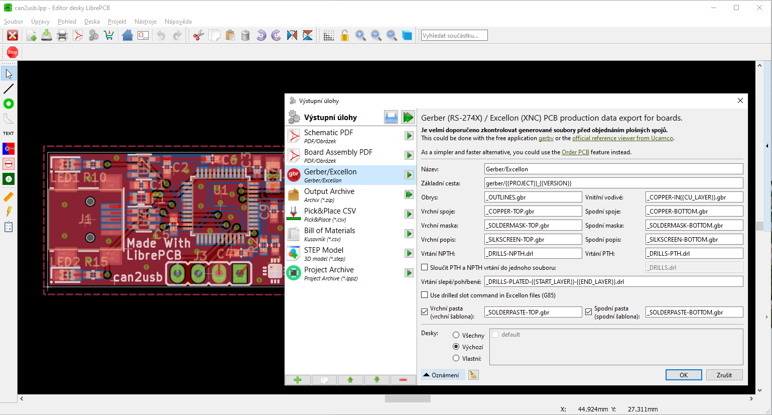
Generation of Production Data
LibrePCB simplifies the process of generating fabrication outputs with an easy-to-use CAM export system. It supports essential formats such as Gerber, Excellon drill files, and BOM, ensuring compatibility with standard PCB manufacturing workflows. While LibrePCB does not yet support advanced fabrication output formats like ODB++ or IPC-2581, it covers the fundamental requirements for most small-scale PCB projects. The tool includes basic DRC checks, but it lacks advanced DFM verification or built-in Gerber viewers, meaning designers may need external tools to verify fabrication files before submission. Despite these limitations, LibrePCB offers a streamlined approach that suits hobbyists and small-scale projects where simplicity is preferred over complex fabrication requirements. An approach to the generation of various output data types in LibrePCB tool is shown on in the following Figure.